- 1. Overview
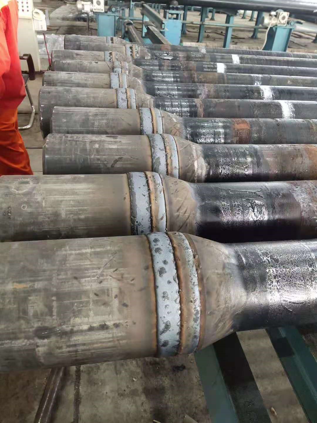
Drill pipes endure intense friction and impact during oil and gas drilling operations. To enhance their wear resistance and service life, wear-resistant bands are commonly welded onto the tool joint surfaces. The quality of this weld directly affects the operational safety and economic efficiency of the drill pipe. Studies indicate that common welding defects—such as cracks, spatter, and porosity—often result from improper process settings, unsuitable filler materials, and inadequate equipment precision. Therefore, a robust welding procedure and a strict quality control system are essential.
2. Welding System Configuration Requirements
System Components
The welding setup primarily includes three major modules: a power supply unit, a pipe rotation mechanism, and a welding torch control system.
Welding Power Source Selection
- Use a gas-shielded DC welding machine with an adjustable voltage of 22–28V and current of 240–320A to suit the characteristics of overlay welding.
- The wire feed system must be stable and adjustable, with moderate tension on the feed rollers. Recommended wire feed speed is 6–12 meters per minute to ensure consistent arc stability and weld quality.
Drill Pipe Rotation Mechanism
- The clamping device must secure the pipe joint firmly during welding to prevent displacement.
- The rotation system should support bidirectional, variable-speed operation, enabling precise control over rotation speed for different welding conditions.
Welding Torch Control System
- The torch holder should provide stable clamping while allowing fine adjustments in both vertical and horizontal directions.
- The oscillation system must support adjustable swing amplitudes of 15–40 mm to ensure uniform weld bead coverage and proper fusion.
3. Filler Wire Selection Criteria
Basic Specifications
- Recommended wire diameters are 1.2 mm and 1.6 mm, with a tolerance not exceeding ±3%.
- Wire should be made from SPCC steel strip via cold-rolling. The surface must be smooth, burr-free, and free from visible defects.
Performance Requirements
- Weld surfaces must be free of through-cracks. Fine shrinkage marks may be allowed but must not extend into the base metal.
- Surface hardness of the overlay should fall within 55–63 HRC, in accordance with the design specifications.
- Each batch of wire must be accompanied by a chemical composition analysis and a certificate of conformity.
- Non-magnetic filler wires must also include a magnetic permeability report to meet specific client requirements.
4. Welding Procedure
Surface Preparation
- Clean the tool joint surface thoroughly to remove oil, rust, and oxidation.
- Mark the weld path accurately according to the drawings to ensure proper placement of the weld bead.
Welding Operation
- Set appropriate welding parameters: voltage, current, wire feed rate, oscillation amplitude, and pipe rotation speed.
- Typically, one to two layers of weld overlay are applied. Each layer must exhibit full fusion, consistent bead formation, and proper contour.
- Preheating may be required (generally 100–200°C) to prevent cracking due to thermal stress.
Post-Welding Treatment
- Allow the welded part to cool slowly to room temperature to avoid structural changes from rapid cooling.
- Remove slag and spatter, and grind the weld surface smooth as needed.
- If required, perform post-weld heat treatment (e.g., tempering) to improve toughness and stability.
5. Quality Inspection and Documentation
Visual Inspection
- The weld surface should be continuous and smooth, free from visible cracks, slag inclusions, or incomplete fusion.
- No visible pores or excessive spatter are allowed.
- Bead width and height must fall within the tolerance limits specified in the drawings (typically ±1 mm).
Hardness Testing
- Use Rockwell or portable Brinell hardness testers to verify surface hardness.
- Conduct at least three measurements in different weld areas, ensuring values meet the specified range.
Non-Destructive Testing (NDT)
- Conduct magnetic particle testing or ultrasonic inspection based on client requirements to detect internal weld flaws.
- Document all test results in formal reports for recordkeeping.
Technical Documentation
- Maintain comprehensive welding records, inspection data, material certificates, and quality assurance documents for project traceability and final acceptance.
This set of guidelines is derived from practical experience and aligned with current industry needs. While it applies to most wear-resistant overlay welding applications on drill pipes, specific adjustments may be made to meet particular project requirements.
Post time: May-28-2025


